Lifting Magnet Systems and Development

I will try to outline the basics of what is involved in running a scrap magnet and what it takes to build and develop a system. I have over 15 years of personal experience and was taught from people that had more than double the experience that I had and they also understood all the principals involved with developing and building such systems. Please keep in mind that I will mostly be talking about the systems and not the magnets and machines that these systems will need to be productive in a working environment.
⚫ Basic Operation
- Supply voltage
• Voltage can arrive from a direct AC line or a generated source like a belt or hydraulic driven generator. Just remember that magnets run on direct current, usually 230 volts DC.
• DC motors can also be used to generate direct current. So a 25hp motor would be similar to a 20kw generator.
• AC Generators and AC line voltage need to be rectified. Small magnets this is a simple task but big magnets will need massive heavy duty costly rectifiers. - Forward and Reverse of the 230 volts dc to the magnet
• Electric scrap lifting magnets need a forward current for lift and a short timed current to drop to clean the magnet.
• Magnets wired directly to the armature of a DC generator will always have the residual voltage of about 6 volts applied to magnet whenever it is off which is a problem for cleaning the magnet after a lift drop cycle and re-entering a pile of scrap with the magnet off, because it will still pick a small amount of steel.
• Note: Switching high voltage DC when the circuit opens a large significant arc is created due to the stored voltage in the coil of the magnet. If the arc is allowed to persist heat is generated quickly and the contacts are destroyed even electronic controlling circuits are now toast. I have lost many multi-meters and other testing equipment due to this also. - Time control for drop time of the reverse voltage
• An adjustable amount of time is needed to clean the steel from the magnet after lifting. This is where the controller comes in. Usually the time needed is just a fraction of a second to a few seconds.
⚫ Systems
- LVF or Low Voltage Field DC Generator
• This system will require a 12 or 24 volt generator. Some generators can be acquired with low voltage fields such as Fuchs, Cat and Baldor. Additionally a DC motor or generator can have the fields rewound to accommodate. Ideally you would want to wind the coils so that when wired in parallel it would work for 12 volts and when wired in series it would work for 24 volts which is the most common. - High Voltage Field DC Generator
• Type 1 is how an Ohio Magnetics system works, the generator voltage is preset to 230 volts DC and the controller switches the output line voltage from the generator to the magnet for lift and drop.
• Type 2 is when a controller is able to drive the field in forward and reverse to achieve lift and drop when the magnet is wired directly to the output line voltage of the generator. - Rectified AC Generator or Line Voltage
• Type 1 is rectified output line voltage using an Ohio controller. Usually a suited rectifier will have to exceed the system requirement by more than double to maintain durability and survive.
• Type 2 would involve driving a field controlled AC generator and controlling the field basically ramping the field voltage up and down between lift and drop cycles and a rectifier with line reversing circuit. - Self-contained Gen-Set
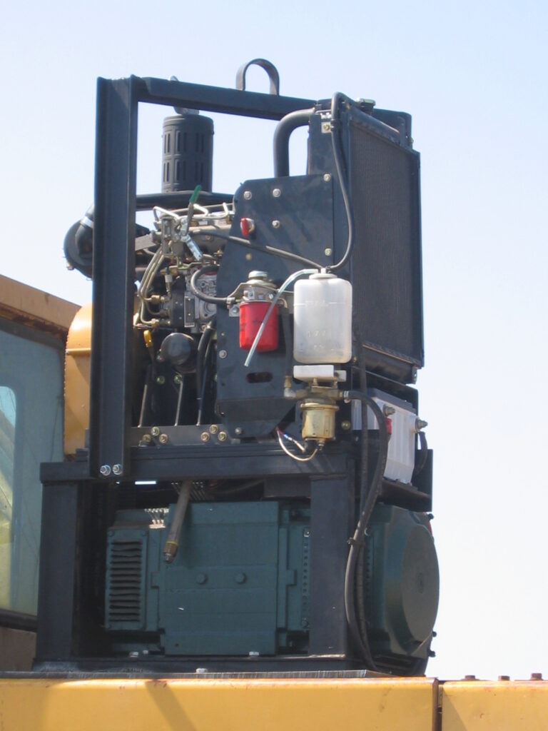
• A system above that is self-contained and run by its own engine preferably a diesel engine connected to the excavators fuel supply. I have built many of these with gas or diesel engines. I also have made systems for forklifts and skid-steers. See illustration 5
⚫ Tools
- Electrical and electrical testing
• The basic Multi-meter, digital and analog are always handy.
• A good set of hand tools (wrenches sockets and pliers snap ring set etc.)
• An oscilloscope is a must for finding voltage spikes and developing complex circuits.
• A good soldering station with board working stands.
• Enamel strippers, compass and wire gauge. Calipers. - Generator Testing and Development
• High capacity load-bank with select-able loads.
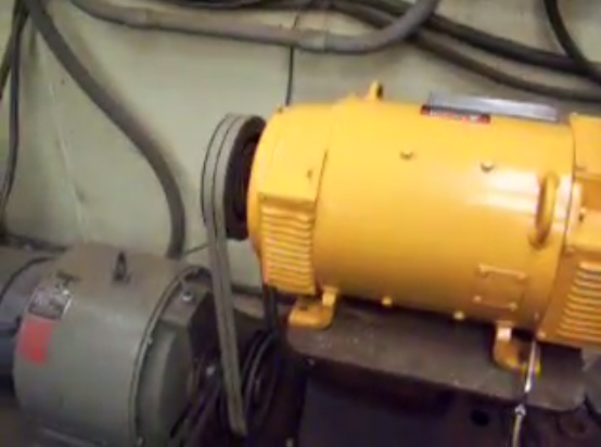
• 60hp electric motor with variable eddy current magnetic drive. See illustration 3
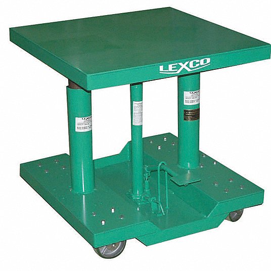
• Hydraulic table for tensioning the belts between the generator and the eddy current drive. See illustration 2
• Metal Lathe for fixing armatures and commutators.
• Bearing heater.
• Various pullers.
• Coil winder Machine with wire feet and turn counter.
• Coil Bender.
• Good supply of Magnet wire.
• Commutator brush.
• Good selection of pulleys. - Controller Testing and Development
• 3 phase 240 volt line service with Variac Variable Transformer. See illustration 1
• 1 phase 120 volt Variac Variable Transformer.
• 3 phase 500 amp rectifier.
• High voltage DC power supply.
• Adjustable bench power supply.
• Small scrap magnet around 15 to 20 ohms for real world testing. - Other
• Mega ohm meter.
• Drill Press.
• Belt Sander.
• Welders and Oxygen Acetylene Torch.
• Milling Machine.
To develop a durable working lifting magnet system it will take time, patients and money. Testing and R&D are key to build a system that will hold-up and provide a lasting profitable service. In my opinion arrived by developing and servicing all manufactures of lifting magnet systems, the best system would be a field controlled AC generator with a controller that ramped up the field to produce a 230 volt output rectified magnet voltage and have the controller automatically monitor and adjust as needed and then have an Ohio style forward and reversing contacts on the output line for the magnet voltage. Another thing that must be considered is that all magnets and generator have a duty-cycle which for a determined amount of on-time requires a determined amount of off time.


