How to use 5050 RGB LED Strip with Arduino
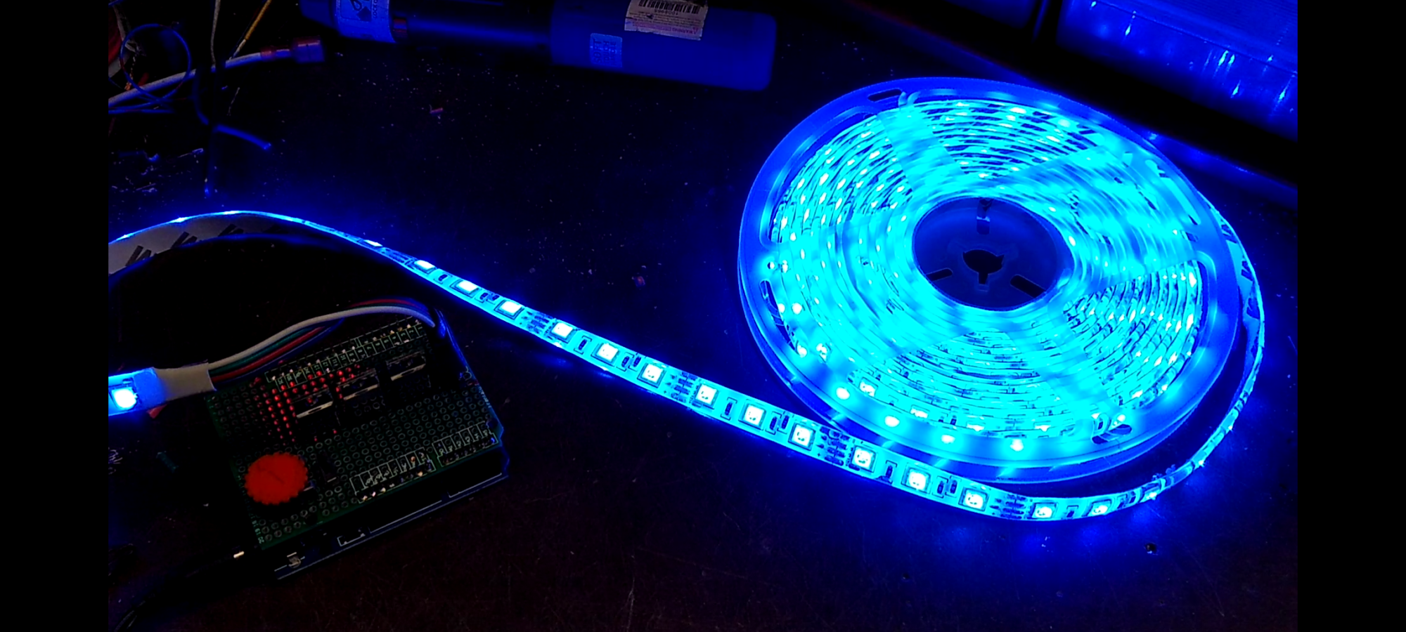
I ordered a couple of these strips on eBay in hopes of making a lighted box sign also I thought it would be cool to play around with but after making a prototype board for my Arduino and trying out other peoples code on the internet I was soon to find out that their code would give blank spots in the color transition some were jittery and some didn’t have a complete color spectrum and one had so many lines of code and so much math involved I just couldn’t figure it out so I decided to simplify and just write my own code.
I simply just rotate through the RGB LEDs with the full range of PWM while reversing the PWM of the last color.
What you will need:
- PC
- USB Cable
- 5050 RGB LED Strip
- Arduino or compatible
- Breadboard or Proto Board
- 3 N-Channel MOSFETs
- 3 Resistors
- 9 to 12 volt Power Supply
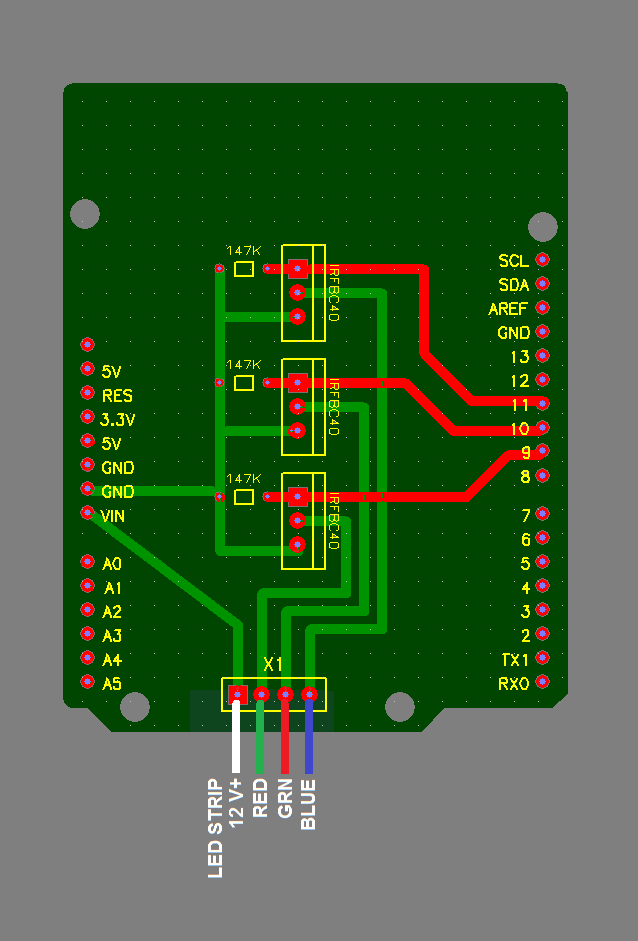
This is a very simple circuit. When selecting the n-channel mosfets just keep in mind the current for a 5 meter strip with my 9 volt adapter was drawing about 800 milliamps so multiple strips and or higher voltage will increase the current. When using n-channel mosfets we need to drive the gate high so we will need a resistor to pull the gate back down to low to stop the current flow I like to use anything around 100k.
I used a 9vdc AC adapter to power the LEDs and the Arduino through the on board barrel power connector and just a note you can power the Arduino and have the AC adapter and the USB cord to program the Arduino all plugged in at the same time.
Below is the Arduino Sketch. You are free to use and modify as you please. You can download it here: UNO_5050_LEDS
// =====================================
// Arduino UNO code to color-fade 12 volt 5050 RGB LED Strip
// By: Pete01507.com
// 12-21-2020
// -------------------------------------
#define green 9
#define red 10
#define blue 11
int spd = 25; //Speed
int cd = 255; //Brightness max is 255
int R = 0;
int G = 0;
int B = 0;
void setup() {
   pinMode(green, OUTPUT);
   pinMode(red, OUTPUT);
   pinMode(blue, OUTPUT);
}
void loop() {
     for (int i = 0; i < cd+1; i++) {
       R=i;
       G=0;
       B=0;
       delay(spd);
        if (R=cd){
          for  (int i = 0; i < cd+1; i++) {
            R=cd-i;
            G=i;
            B=0;
            delay(spd);
            LEDS();
          }
        }
       if (G=cd){
          for  (int i = 0; i < cd+1; i++) {
            R=0;
            G=cd-i;
            B=i;
            delay(spd);
            LEDS();
          }
        }
       if (B=cd){
         for  (int i = 0; i < cd+1; i++) {
            R=i;
            G=0;
            B=cd-i;
            delay(spd);
            LEDS();
         }
       }
       LEDS();
    }
}
 void LEDS () {
  analogWrite (red, R);
  analogWrite (green, G);
  analogWrite (blue, B);
}