PIC Microchip Microcontroller LED Turn Signal Flasher PIC16F872
This project we will make a LED turn signal flasher. I made this because I installed LED light bulbs in my car to save ware and tare on the alternator but a normal flasher will not flash LED bulbs. You can use whatever processor you want but I used a PIC16F872 because at work we discontinued using them at work and we upgraded to PIC16F886 so I can get these at a discounted price.
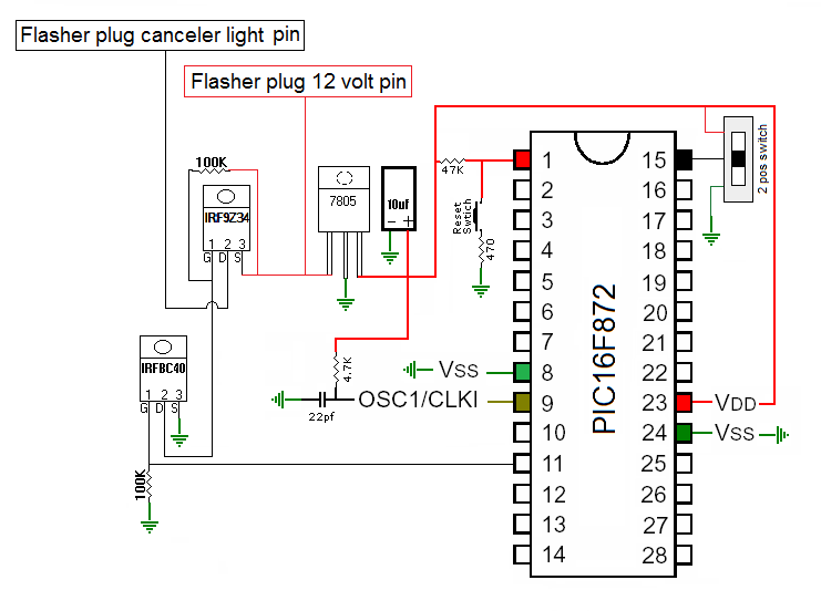
It’s a really simple circuit and it can be built differently but this is how I built it. The switch allows for two different modes on for normal flash and one for a quick triple flash. The connections are made at the flasher plug and a ground connection the output of the P-channel mosfet goes to the turn signal canceler side of the plug and the 12 volt power comes from the other side of the flasher plug and the a ground.
The MPASM Assembly code:
; 872-TurnSignal 5-3-16
; LED Turn Signal Flasher
; by Pete01507
; RB7 low = normal flash
; RB7 high = TFF flash "triple flash fast"
	include "p16f872.inc"
	__CONFIG _FOSC_EXTRC & _WDTE_OFF & _PWRTE_OFF & _CP_OFF & _BOREN_OFF & _LVP_OFF & _CPD_OFF & _WRT_OFF
	errorlevel-302   	;removes error 302 during build
bank0   EQU  0x00
bank1	EQU  0x80
bank2	EQU  0x100
bank3   EQU  0x180
	cblock 20h
delay1        			; Define 8-bit variables for the
delay2       			; delay loop: Delay1 and Delay2
	endc
	org 0h
 	banksel	bank1		; same as STATUS,5
	movlw	b'00000000'	; configure PORT C as output (1=input,0=output) bit order='76543210'
	movwf	TRISC		; moves your configuration of PORT C
	movlw	b'11111111'
	movwf	TRISB
	banksel	bank0		; same as bcf STATUS,5
	clrf    PORTC
	clrf	PORTB
start
	btfsc	PORTB,7
	goto	ff
reg
	bsf     PORTC,0		; sets PORTC,0 high
	call    delay		; call subroutine delay
	call	delay
	call	delay
	bcf     PORTC,0		; sets PORTC,0 low
	call    delay		; call subroutine delay
	call	delay
	call	delay
	goto    start		; continous loop
ff
	bsf	PORTC,0
	call	delays
	bcf	PORTC,0
	call	delays
	bsf	PORTC,0
	call	delays
	bcf	PORTC,0
	call	delays
	bsf	PORTC,0
	call	delays
	bcf	PORTC,0
	call	delays
	call	delay
	call	delay
	call	delay
	call	delay
	call	delay
	goto	start
delay
	movlw	.255		; use value .1 to .255 low numbers = fast large numbers = slower
	movwf	delay2
delayloop1
	movlw	.255		; 255 is the maximum number
	movwf	delay1
delayloop2
	decfsz	delay1,f	; decrease file size skip if zero loops until 0 then skips next instruction
	goto	delayloop2	; this is skipped until delay1 reaches 0 then this instruction is followed
	decfsz	delay2,f
	goto	delayloop1
	return			; return from subroutine
delays
	movlw	.100		; use value .1 to .255 low numbers = fast large numbers = slower
	movwf	delay2
delayloop11
	movlw	.100		; 255 is the maximum number
	movwf	delay1
delayloop22
	decfsz	delay1,f	; decrease file size skip if zero loops until 0 then skips next instruction
	goto	delayloop22	; this is skipped until delay1 reaches 0 then this instruction is followed
	decfsz	delay2,f
	goto	delayloop11
	return			; return from subroutine
	end
The components you will need. Most of the these can be substituted for equivalent components.
- Processor
- Processor socket
- PCB board
- 7805 voltage regulator
- 10uf capacitor
- 22pf capacitor
- PCB switch
- IRFBC40 N-channel MOSFET
- IRF9Z34 P-channel MOSFET
- 2- 100k resistors
- 1- 4.7k resistor
- 1- 47k resistor to pin 1 reset switch & 470 optional
- 2- male 1/4″ PCB spade connectors
- 1- 20ga wire for ground

