Programming a PIC Microcontroller in Assembly Code, Blink an LED PIC16F877A
PIC Project #1 “Blink”
This code is useful for such projects as a car turn signal flasher for when you upgrade to LED lights. Another project I am working on is a garage door opener controlled with my phone and Bluetooth App using a PIC16F872. The instruction set for the 16F pic’s is very similar but you should always download and check the datasheet. I have used this code with 877A, 872 and 886. The PIC16F886 is nice because it has an internal oscillator.
ⓘ The Lesson
Most important when beginning and learning is just starting simple and making sure that we can actually get our processor programmed.
Getting Started: The Basics
You will need to download and install the Microchip MPLAB IDE once installed click the File Menu select New Project.
Step 1: In the Choose Project tab choose the Microchip Embed and Standalone Project and click Next.
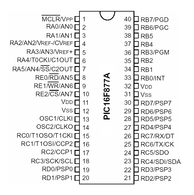
Step 2: In the Select Device tab choose Mid-Range 8-Bit MCUs and your processor and in this case for this example we will use a PIC16F877a and click Next.
Step 3: In the Select Header tab just click Next.
Now it will skip to Step 6: Select Compiler tab, choose the mpasm compiler and click Next.
Step 7: In the Select Project Name and Folder tab, name your project and select your folder. In this case I will name my project Blink and use the default folder created for us and click Finish.
Now your project folder and files will be in the left side Project Window of the IDE. Now we need to create our Assembly file. Hover your mouse over your project name and right click your mouse and select the New tab and select the pic_8b_simple.asm option. Next name your file in this example we will name the file “blink” and leave the folder option blank. Now you have an IDE generated assembly file. You can always create an assembly file from your favorite text editor and use the add files to project option. This generated assembly file will have some auto-generated code which we will delete so we can start fresh.
Delete everything and start with a small commented header that has information on the Programmer and any details about the code like I have below. The semi-colon is used for commenting.
; Blink an LED By: Pete01507 10-20-2020
; Assembly program for PIC16F877A
; Blink an LED on RC0
Next is the Code the first line we need is the include line:
include "p16f877a.inc"Next we need to set the “Configuration Bits” the next line will be as listed below:
__CONFIG_DEBUG_OFF&_CP_OFF&_WRT_OFF&_CPD_OFF&_LVP_OFF&_BODEN_OFF&_PWRTE_ON&_WDT_OFF&_RC_OSCI like to have neat and organized code structure. I define the data banks and variables. Next insert the code below.
bank0	EQU  0x00		; control bank
bank1	EQU  0x80		; manipulate the data bank
bank2	EQU  0x100
bank3	EQU  0x180
	cblock 20h		; bank0 20h to 7fh
delay1        			; Define 8-bit variables for the
delay2       			; delay loop: Delay1 and Delay2
	endc			; end of variables
Next we need to tell the complier where we will place our main source code with this statement:
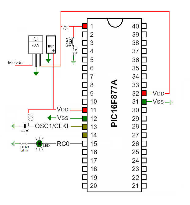
org 0x00Next we need to setup the port we are going to use.
banksel	bank1		; same as bsf STATUS,5
movlw	b'00000000'	; configure PORT C as output (1=input,0=output) bit order='76543210'
movwf	TRISC		; moves your configuration of PORT C
banksel	bank0		; same as bcf STATUS,5
Now the code!
start
	bsf     PORTC,0		; sets PORTC,0 high
	call    delay		; call subroutine delay
	call	delay		; more on time
	call	delay		; more on time
	bcf     PORTC,0		; sets PORTC,0 low
	call    delay		; call subroutine delay
	call	delay		; more off time
	call	delay		; more off time
	goto    start		; continous loop
delay
	movlw	.255		; use value .1 to .255 low numbers = fast large numbers = slower
	movwf	delay2		; move value to cblock variable
delayloop1
	movlw	.255		; this number should match the one three lines above
	movwf	delay1		; move value to cblock variable
delayloop2
	decfsz	delay1,f	; decrease file size skip if zero loops until 0 then skips next instruction
	goto	delayloop2	; this is skipped until delay1 reaches 0 then this instruction is followed
	decfsz	delay2,f	; decrease file size skip if zero loops until 0 then skips next instruction
	goto	delayloop1	; this is skipped until delay1 reaches 0 then this instruction is followed
	return			; return from subroutine
	end			; end of program
Here is the complete code.
; Blink an LED By: Pete01507 10-20-2020
; Assembly program for PIC16F877A
; Blink an LED on RC0
   	include "p16f877a.inc"
	__CONFIG _DEBUG_OFF&_CP_OFF&_WRT_OFF&_CPD_OFF&_LVP_OFF&_BODEN_OFF&_PWRTE_ON&_WDT_OFF&_RC_OSC
bank0	EQU  0x00		; control bank
bank1	EQU  0x80		; manipulate the data bank
bank2	EQU  0x100
bank3	EQU  0x180
	cblock 20h		; bank0 20h to 7fh
delay1        			; Define 8-bit variables for the
delay2       			; delay loop: Delay1 and Delay2
	endc			; end of variables
	org 0x00		; code starts at this address (reset vector)
	banksel	bank1		; same as bsf STATUS,5
	movlw	b'00000000'	; configure PORT C as output (1=input,0=output) bit order='76543210'
	movwf	TRISC		; moves your configuration of PORT C
	banksel	bank0		; same as bcf STATUS,5
start
	bsf     PORTC,0		; sets PORTC,0 high
	call    delay		; call subroutine delay
	call	delay		; more on time
	call	delay		; more on time
	bcf     PORTC,0		; sets PORTC,0 low
	call    delay		; call subroutine delay
	call	delay		; more off time
	call	delay		; more off time
	goto    start		; continuous loop
delay
	movlw	.255		; use value .1 to .255 low numbers = fast large numbers = slower
	movwf	delay2		; move value to cblock variable
delayloop1
	movlw	.255		; this number should match the one three lines above
	movwf	delay1		; move value to cblock variable
delayloop2
	decfsz	delay1,f	; decrease file size skip if zero loops until 0 then skips next instruction
	goto	delayloop2	; this is skipped until delay1 reaches 0 then this instruction is followed
	decfsz	delay2,f	; decrease file size skip if zero loops until 0 then skips next instruction
	goto	delayloop1	; this is skipped until delay1 reaches 0 then this instruction is followed
	return			; return from subroutine
	end			; end of program
After you are done writing the code you need to build it from the Run tab to compile it into a HEX file so you can burn it to the microcontroller. I use a JDM programmer with PICPgm on my desktop because it has a Serial port and I use a PicKit 3 programmer on my laptop. The PicKit is probably the best because you can integrate it with the MPLAB.
PIC16F877A 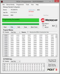
PicKit 3 Software 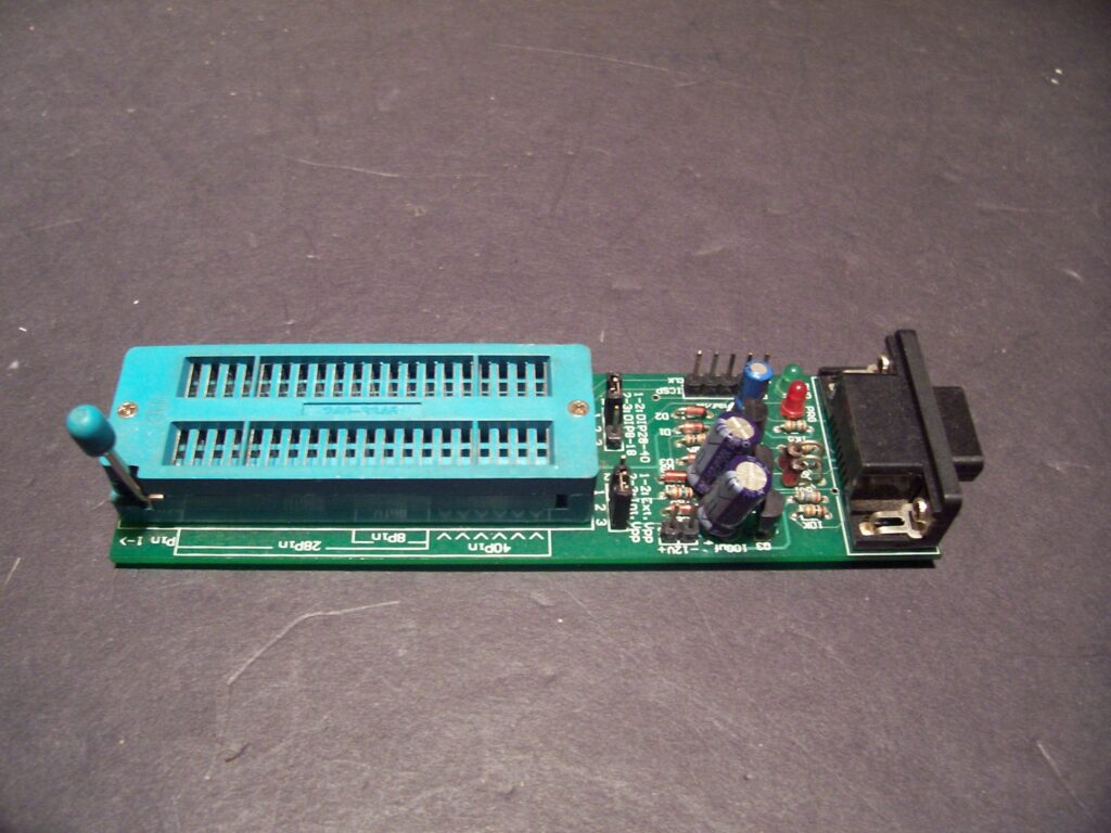
JDM Programmer 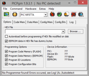
PICPgm for JDM Programmer 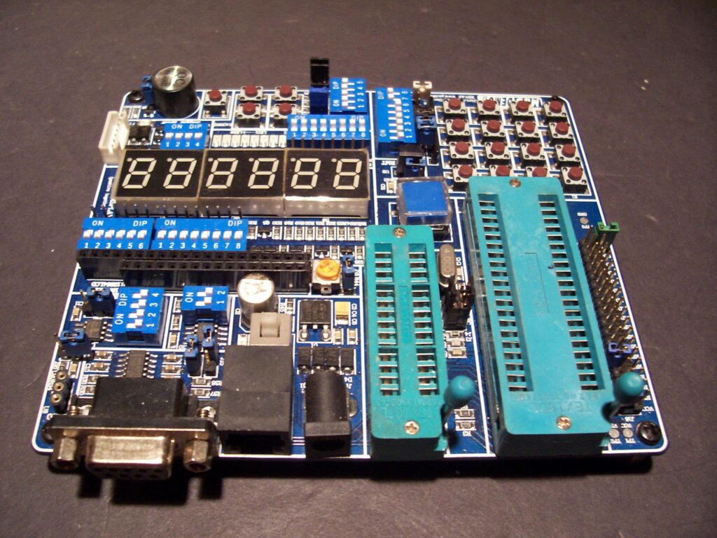
PIC Development Board
I have more to add to this post but I will publish it for now. I also plan to have a complete PIC series of posts. Please feel free to comment or ask questions. Thanks